
- Modelsim tutorial video pro#
- Modelsim tutorial video software#
- Modelsim tutorial video code#
- Modelsim tutorial video license#
# End time: 15:13:57 on Sep 12,2021, Elapsed time: 0:00:01Īnd this was the code: entity T01_HelloWorldTb is

This was the output of the transcript: ModelSim> vsim -gui work.t01_helloworldtb

You can unselect device support for everything except.
Modelsim tutorial video software#
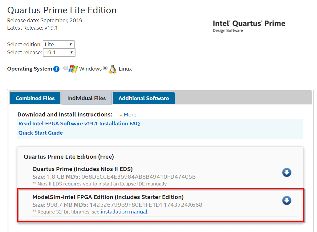
This is for my lab work and I think ModelSim is the only free software for VHDL programming out there. Before downloading, make sure the ModelSim option is selected. I've looked it up everywhere, but I still couldn't find the solution. There was no compilation error, but every time I started the simulation, an error loading design always showed up. Also see If we hear, we forget if we see, we remember if we do, we understand. Wiley and Sons, 2007.Concise (180 pages), numerous examples, low-cost. After I made a new project in the original folder (intelFGPA), I wrote a simple hello world. VHDL Tutorial: Learn by Example- by Weijun Zhang, July 2001 NEW (2010): See the new book VHDL for Digital Design, F. I have msi.dll on my computer and I've tried downloading a new one. After I downloaded the ModelSim, it showed a vml.exe error that says "the msi.dll is missing". The figure of internal components is huge and its not possible to show it in single picture so i removed it.I'm learning VHDL by following a YouTube tutorial.
Modelsim tutorial video license#
7:31, 30MB, Instructional video on obtaining license and installation.
Modelsim tutorial video pro#
The internal circuit is composed of xor gates flip flops and other components. Synthesis: Synopsys Synplify Pro Simulation: Mentor ModelSim Lattice Edition. But i bet you if you try to write them on paper and do the logic xor manually you can easily understand whats going on in.Ħ-bit gray counter main entity is shown below. Important: The above logic is hard to explain. This next state is transferred to current state on next rising edge of clock. The current state is assigned to the output and next state is calculated. The result is placed in Nextstate variable Nextstate <= next_hold XOR (‘0’ & next_hold(N-1 DOWNTO 1)). In the third statement we perform the same concatenation and logical xor but this time on next_hold variable. The result is placed in next_hold variable next_hold <= std_logic_vector(unsigned(hold) + 1). In the next statement we increment the hold by 1. The result is placed in hold variable hold <= Currstate XOR (‘0’ & hold(N-1 DOWNTO 1)). We then xor this current state with the 5 lsb(least significant bits) of current state while concatenating the 0 at msb(most significant bit) of current state. I will give it a try.Īfter reset the current state value is 000000.
Modelsim tutorial video code#
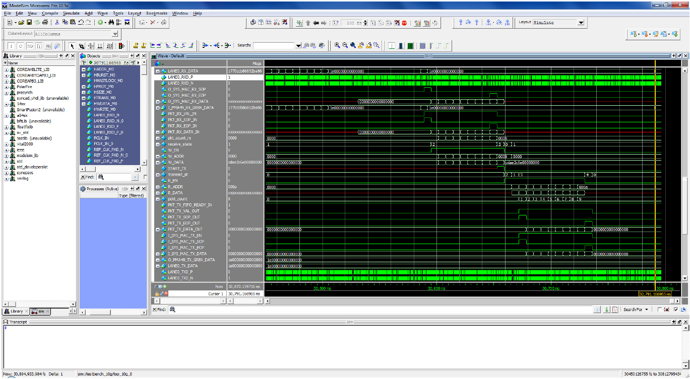
I am sure its not possible for me to write the logic for those three code statements which you can pick up and easily understand. Well the code part after process is generating the next gray code value for us. How the gray counter is incremented in vhdl case? In the absence of clock you cant reset the system.Ĭoming to the main and complex logic. The reset is synchronous which means that reset execute on positive edge of the clock. These signals are used to hold the values manipulated for gray counter by finite state machine. In the architecture part few signals are defined. (6) state machine (6) testbench (6) block RAM (5) file handling (5) synthesisable (5) fixed point package (4) port mapping (4) video tutorials (4) arrays and records (3). Libero SoC PolarFire and Libero SoC v11.8 or later now include ModelSim Pro. With this new edition of the simulator, Microsemi introduces mixed-language simulation for Verilog, SystemVerilog, and VHDL. clock, reset and enable are 1-bit inputs. You should get the following waveform when you simulate the codes correctly. Libero SoC v11.8 comes with a new simulator: ModelSim Pro ME which provides enhanced simulation capabilities. Notice that the output port size is dependent on the generic variable N. Clock, reset and enable signals are input to the entity and the only output is our gray code. You can change it according to your need. In my case i want a 6-bit gray counter so i initialized it with 6. The generic variable is used to declare the size of the gray counter. In the main entity first a generic N: integer:=6 is defined. If you don’t know about finite state machine and how it works? Then before moving any future i will suggest you to first take some tutorials on fine state machine and how it works? I also assume that you are well aware of FSM(finite state machine). I assume that you now what is meant by current state and next state logic. The counter is designed on current and next state logic.

The main gray counter entity vhdl code is given below.


 0 kommentar(er)
